What we did at the weekend! (aka. Hackathon VI - Return of the Pi)
This weekend we held the 6th Cosmic Pi team Hackathon at CERN. This means that we've spent 6 whole weekends (and probably a few more!) designing, building and testing our designs for Cosmic Pi. As any experimental physicist will tell you, building hardware comes with it's fair share of disappointments along the way, but this weekend we had some successes. Here they are:
Analogue PCB Testing
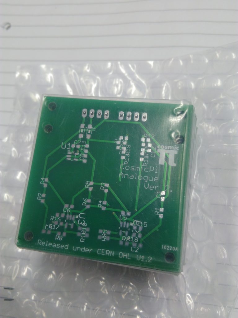
Our analogue front end PCB prototypes arrived a two weeks ago from SEEED studio.
We designed a new Analogue front end Printed Circuit Board a few weeks ago, had them fabricated by SEEED in China and shipped to us in Switzerland. The design comprises of a 50x50mm mezzanine card, featuring two Silicon Photomultipliers (SiPM) - the light detecting modules in a Cosmic Pi - on one side, and a pair of low power, high bandwidth amplifiers on the other. The board is designed to be glued to a slab of scintillator (the special plastic tile that emits photons of light when Muons pass through it). The inputs to the board are three: +5V (from the Arduino DUE), +Vbias (approximately 30V, which will come from our Main PCB, but for these tests we used an external 35V power supply) and Ground. The outputs are two single channel analogue signals, which are read into the Analogue to Digital Converter (ADC) on the Arduino DUE. Normally the board will plug into the top of our main PCB, sitting on top of the scintillator - but the spacings of the pin headers are set out such that it can also plug straight into an Arduino to facilitate testing.
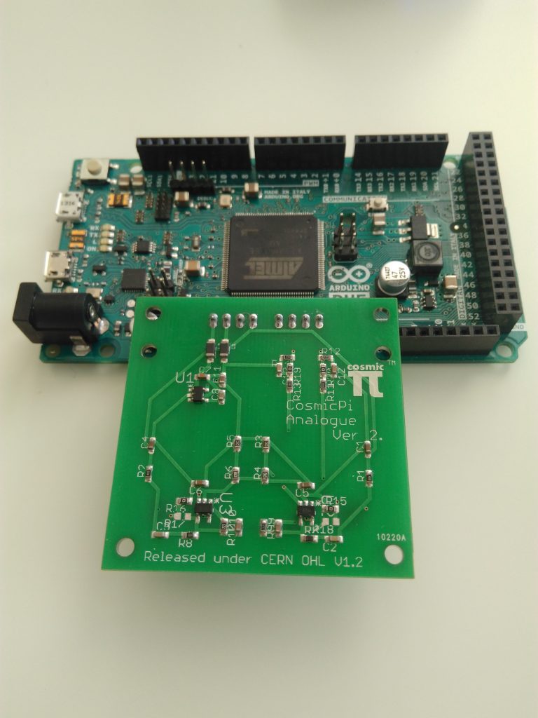
One plugs in to the other one to facilitate testing!
We tested a few different aspects of the circuits:
- 4 V power supply - After talking with an analogue electronics expert, he recommended that we introduce a separate voltage rail with a Low Dropout regulator (LDO) to enhance noise immunity from the potentially very noisy 5V rail (which comes in from the USB plug on the Arduino). We checked this and it was within the tolerance (actually just a touch below 4V) on both the prototype PCBs.
- SiPM Voltage and output signal - to ensure that the breakdown voltage was applied across the diode. Initially we had some problems as we couldn't get the voltage across the diode above 26 V, no matter how much we put into the Vbias pin. Initially I suspected that one of the capacitors was breaking down due to a 25V breakdown voltage, however research indicated that actually the breakdown failure mode of a capacitor is generally to short circuit, which would have given us 0 V. I changed the capacitors just in case, it didn't have any effect so I changed them back again. The actual cause was the bias resistor, inserted to limit the current in the SiPM and prevent damage. Our initial design used 100k Ohms as we'd seen high values in other people's designs. However we changed it to 40.2 Ohms and after that everything worked as expected, with almost the full Vbias appearing across the SiPM.
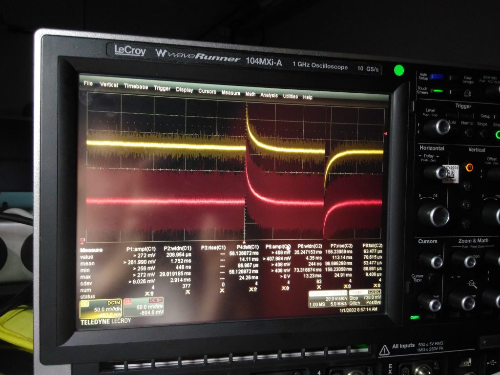
- Amplifier performance - each SiPM has an analogue amplifier which uses the AD8014 SOT-32 amplifier chip (we were inspired by this thesis, thanks to Johannes Schumacher for replying to our email questions!), used to both stretch and amplify the very rapid signal from the SiPM into something which can be sampled using our ADC. The first test of the amplifier was the output bias voltage, which was measured to approximately 450 mV in the quiescent condition (no input signal). When a signal was applied (either by shining light on the SiPM in the presence of a Vbias, or by coupling it with the scintillator), a corresponding pulse of between 20-40 mV was seen on the signal output. This was more or less as predicted by the LT Spice model - which is available in our analogue package zip file here. The SiPM input signal was slightly larger than expected (200 mV rather than 140 mV as we initially guestimated), but the timing parameters were accurate (approx 5 ns rise and a slightly longer decay). The performance of the amplifier was somewhat compromised by the presence of significant noise (100 mV peak, at 100 kHz), however we still managed to see some interesting things by carefully setting the trigger on our scope.
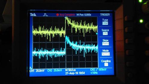
These pulses were obtained by manually triggering the scope. There is a large amount of noise from the bench power supply, but it still has a good probability of being a cosmic ray due to the simultaneous triggering of both SiPMs.
We later made some modifications to two of the resistors that control the gain and pulse shaping function of the amplifier. This provides a higher peak voltage (up to a few hundred mV for our reference signal), at the expense of a shorter duration pulse (down to about 7 uS from more than 10 uS). However, given the noise performance we observed this is a trade off well worth making. We have 48 of these individual PCB's left over (unpopulated). If you are interested in getting hold of one let us know, as we are currently trying to figure out what would be the best use of them. In this version the mounting of the SiPM really needs use of a reflow oven, but we do plan to add socket connection points to a future version making it more home assembly friendly. Our next batch of these boards will be panelised to make volume production possible.
At this point we should also thank our follower Philipp Foedisch for sharing his comments on our analogue design with us before we assembled it. He pointed out that the datasheet for the AD8014 specifies a minimum rail-to-rail voltage of 4.5 V (and we're driving it at 4 V) and a minimum input bias voltage of 1.1 V to 3.9 V. Our design is slightly outside both of these parameters, however as you can see from the oscilloscope traces, it still meets our functional requirements. We are now reviewing whether to keep the 4 V rail, but we have decided to keep the input bias voltage the same (at least as a potential divider ratio based on the amplifier supply voltage). We have included a non-mounted 0 ohm resistor to bypass the 4 V LDO, however changes to the gain resistor network mean that we risk saturating if we increase the bias input voltage too much. Before assembling and testing our hardware, we also looked up some <4 V tolerant SOT-23 amplifiers, such as the AD8057 but for the moment we will be keeping our current amplifier. Changing the amplifier might also be an option in the future to reduce the BOM cost of this PCB module.
With the scintillator and analogue board assembled and connected to an Arduino, with the Vbias pin carefully removed and connected to an external 32 V power supply, we were able to operate the system as a cosmic ray detector, by creating a software trigger with a variable threshold in the Arduino. Note that the removal of the Vbias pin is essential, as connecting a 32 V supply to the Arduino's Vin pin is likely to completely destroy it. This simplified detector isn't the main aim of our project, but does provide a great proof of concept for a simplified scintillator cosmic ray detector. Here is a video of it in operation and the code for our software trigger is now in a gist on github.
Scintillator
We wrapped a pair of our EJ-200 scintillators and coupled them to the SiPM's using Araldite clear epoxy resin. One of the joints was a success, the other had to be re-done twice - it turns out that Acetone is a good solvent for epoxy and should be used with a lot of care and very sparingly when cleaning optical components before gluing! We tested one of the slabs by reading out the signal via the SiPM and amplifiers, which gave us some likely cosmic ray candidates. We also tested light injection, using the LED flash of our mobile phones, and then a more sophisticated fibre optic light injection system. These tests confirmed that the slab was well coupled to the SiPM sensors.
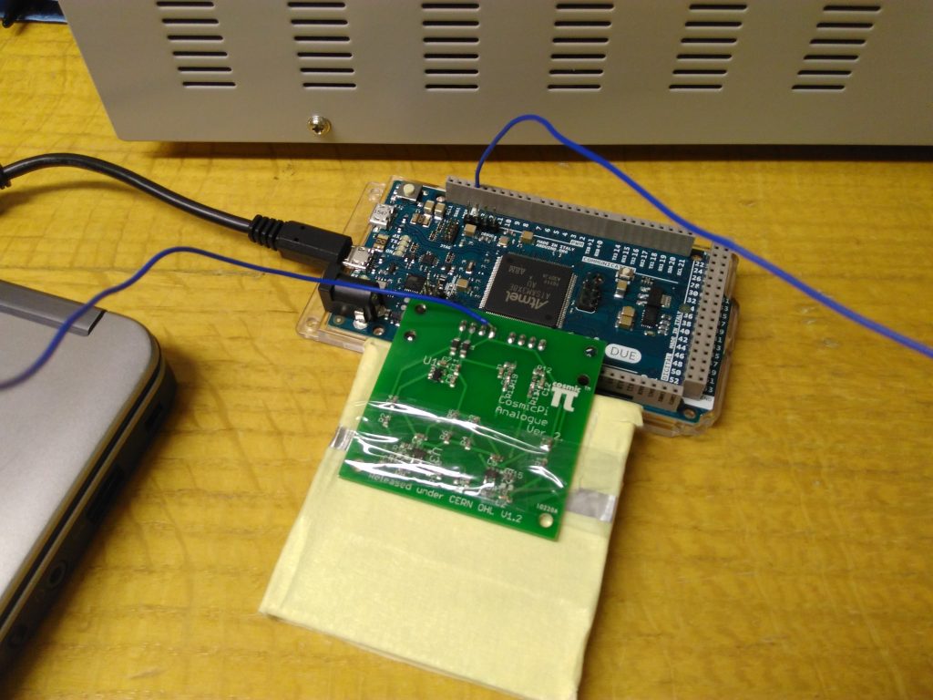
A wrapped scintillator coupled to an Arduino Due with an external 32 V power supply
The light injection waveform was studied using a high speed oscilloscope, showing saturation of the SiPM at high light levels. We thought we had better do this test using a proper light injection set-up, however we had tried it earlier using a camera phone flash - and it worked. However the LED light injection system is configurable, both in terms of the intensity of light injected and the frequency and duration of the pulses, making it much better for obtaining a precise understanding of the system performance.
2016-08-28 22.06.26
In response to the success of the light injection tests we have added a 2mm thick (so as to be the same height as the SiPM modules) LED to our next generation analogue PCB. This will enable us to pulse red and blue light into the scintillator and verify the coupling of production units in a non-invasive way.
Zero Point Five Baseline
As our regular readers will already have seen, we did a 'zero baseline' experiment a few weeks ago to demonstrate the timing performance of our system using GPS as a reference. The zero baseline is comparatively simple, as all the data can be gathered by simply logging the serial data to a single computer over USB. We decided to do another test, this time with the two systems geographically separated. This adds the complexity of using the internet to send the signals to a single common point (our server), requiring a local script on each system and another to suck in the data on the server and log it. At the moment we're doing this using Python and the UDP protocol.
Of course, we're no longer able to provide the same trigger signal to both systems simultaneously - as we don't have a very long cable! Therefore each system gets a trigger pulse which is regenerated from the GPS pulse per second signal with a delay of approximately 249 ms, generated by a second Arduino DUE. The exact delay of the second pulse is subject to the operation of the second Arduino's internal clock, so exhibits some drift with temperature. However, the purpose of this test is to demonstrate the overall reliability of our system when operated at two different locations, and our capacity to send back to a server, rather than to measure the temperature performance of an Arduino. This test is a prelude to our Long Baseline test which we'll be doing in the near future. It will involve a high accuracy simultaneous pulse arriving at two systems in different locations approximately 20 km apart - we are fortunate to have friends with some very long wires!
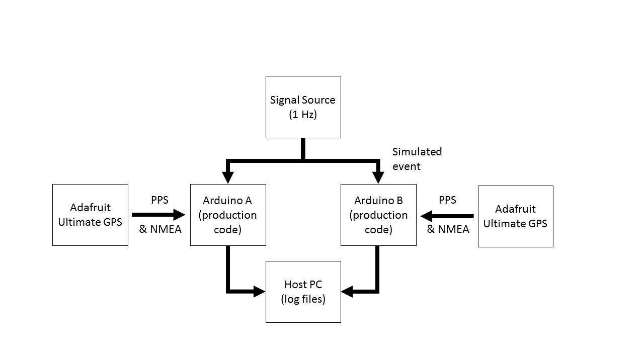
A recap of the principles of the Zero Baseline test
Here are some raw results from our zero point five baseline, taken from a preliminary run lasting only a couple of hours. A 48 hour test is running as I speak, we'll make the data available as soon as we can.
What's next?
So far we have validated and improved our design for the analogue PCB. If you want to build your own you can get our improved version 2.1 design here. If you've already started building a V2, don't worry - it works fine as described here. Our next objective will be to assemble our Main PCB V2 Alpha and test this, however we're waiting for our prototype PCB's to arrive from China and a few other longer lead components (GPS modules and the MAX1932 chip we're using to generate Vbias).
When we have all the components and access to the machines for assembly, we'll have yet another hackathon to test the many functions of this board (GPS, Timing, Triggering, Humidity, Temperature, Acceleration, Magnetic Field sensing, Bias voltage generation, physical form factor and fitting into our housing, connections to the Arduino and anything else we can think of). If everything goes well then we'll start production of our first units for the CERN Beamlines for Schools competition runner-up prizes, and if we have any major issues we will revise our Main PCB and repeat when the new boards arrive. Until then we can be confident that the detection hardware is on a solid footing and catch up on some sleep!

Probing the analogue PCB for signals from the amplifiers.