Hackathon 6: Testing the Main Board
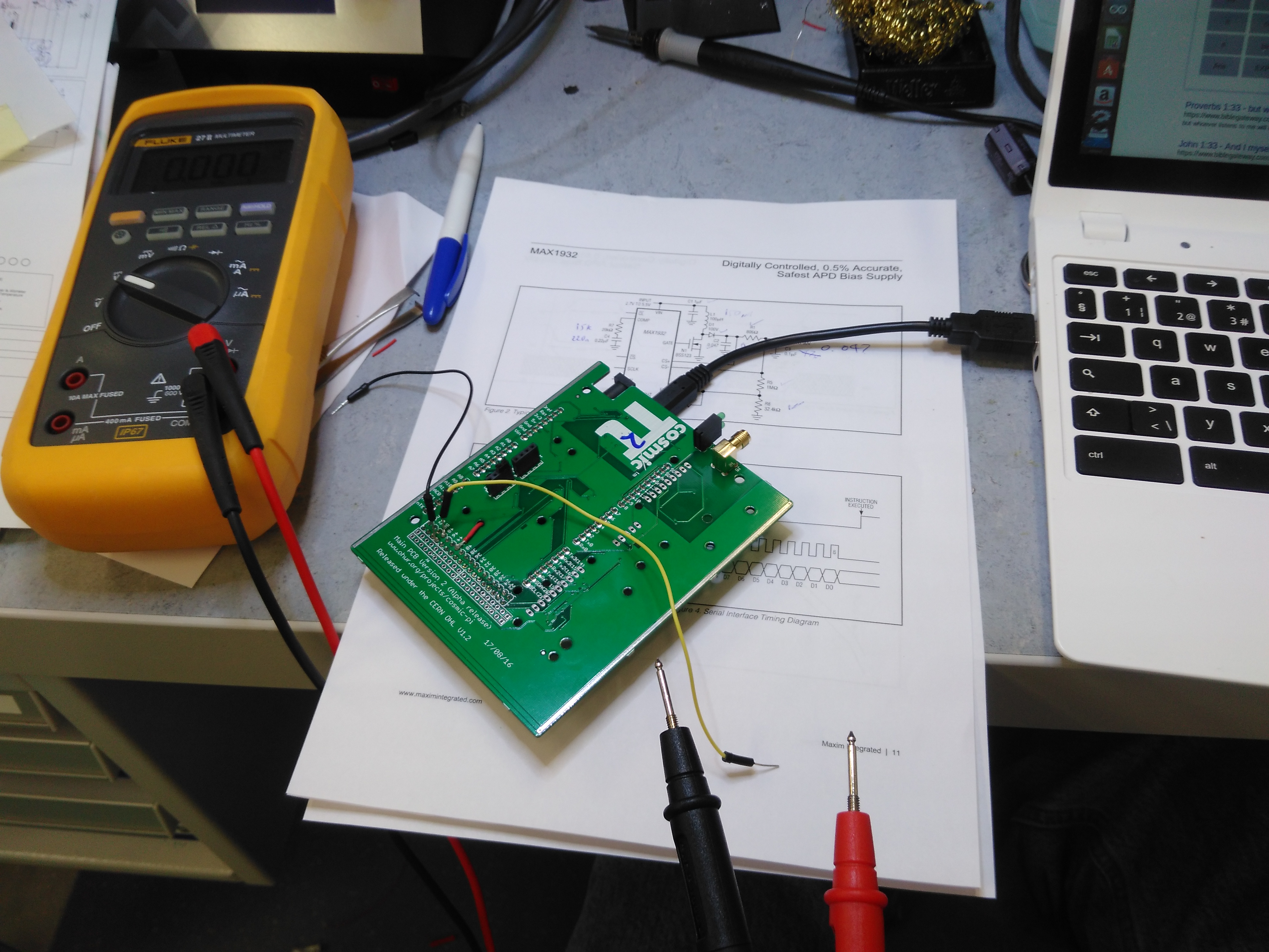
Test probes
This weekend we finally got our hands on our fully assembled Main Board PCB's. They provide the core functionality that makes Cosmic Pi work, specifically:
- GPS to locate the unit in time and space
- Altimeter to confirm the altitude (and help predict the weather!)
- 3 Axis accelerometer & magnetometer to confirm the orientation of the box
- Temperature and humidity sensor to check the local environmental conditions and monitor the plastic scintillator
- Boost Power Supply, to provide the bias voltage for the Silicon Photomultiplier sensors
- Voltage reference and variable trigger threshold generation with two comparators and trigger output
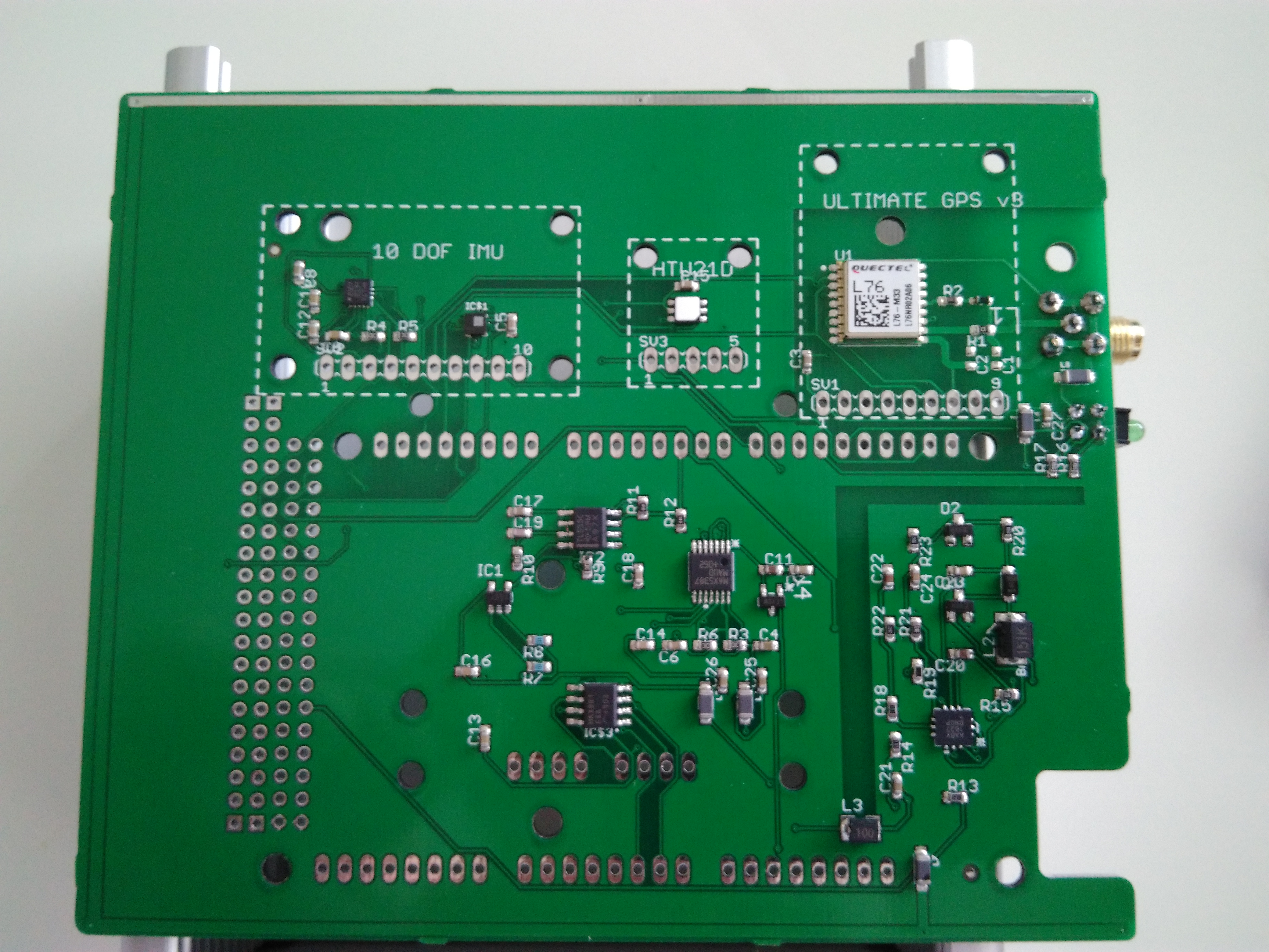
Main Board - Bottom
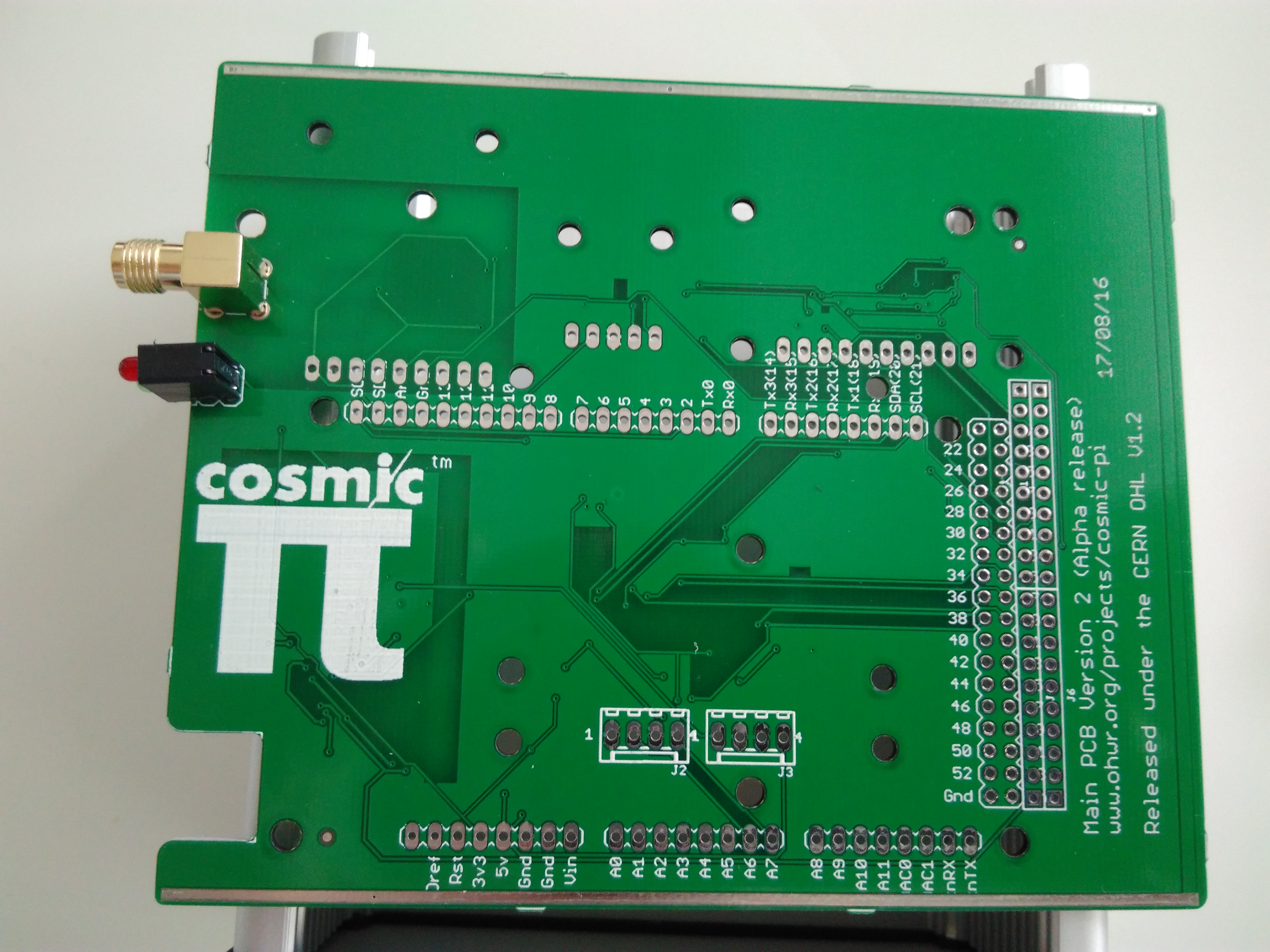
Main Board - Top
We tested the systems on the basis of their electrical connection to the Arduino Due which sits undernea
th the main board. In fact we use the following busses to talk to the peripheral devices:
- UART (bus 1) to talk to the GPS (RX/TX at 9600bps)
- I2C (bus 0) to talk to the variable threshold circuit (actually a MAX5387 digital potentiometer)
- I2C (bus 1) to talk to the Accelerometer, Pressure Sensor and Humidity Sensor
- SPI (using bit-banging) to talk to the Boost Power Supply
Over the weekend we tested a number of systems, using a production test system specification we've been working on for the last few weeks. The basis of the test is to prove the electrical connections to each item of hardware or sub-system, such that we can validate our design in the first instance, and the production units in the second. So far we've done the following tests on the hardware:
- GPS - confirm position, bi-directional communications and firmware version for the receiver (Quectel L76) - Working
- Variable trigger - setting digital potentiometer threshold and reading back the value with a digital volt meter
- Accelerometer, Pressure Sensor and Humidity Sensor - validation of communications to addresses over the I2C bus
- Boost Power Supply - setting voltage value via big-banging SPI protocol over discrete pins and reading the voltage back with a digital volt meter
- Trigger output - application of a simultaneous analogue signal to both inputs to confirm the creation of a trigger pulse
You can watch all our video lab reports on our Cosmic Pi YouTube channel. Although we now have all the hardware working, we picked up a few bugs in the design along the way. Here's a headline summary for anyone who's already built/building their own Version 2 alpha main board (if you are please get in touch!):
- Missing !CS signal from Arduino DUE to MAX1932 boost power supply controller, we had to add an extra jumper wire from a DUE pin.
- 4.096V reference too high for the MAX5387 to operate correctly, to be swapped for a 3.3V reference.
- Feedback resistors for the MAX1932 incorrectly chosen, to be modified to provide correct voltage output range (25-35V)
- Trigger NAND gate replaced with an AND gate (same IC package, different logic)
- Front panel LED's swapped from 2 LED module (Red/Green) to 2 LED module (Green/Green) due to wrong anode/cathode configuration
A more comprehensive list of the bugs in Main Board Version 2 alpha can be found here.
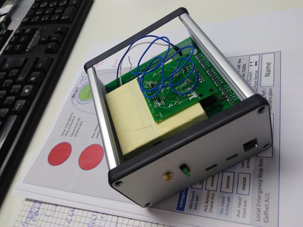
All in the box!
We will soon be fixing all these things on our main board schematic and layout in a Version 2 release of the main board, which will include the replacement part numbers and all the necessary details to build your own.