(Alpha) Design for front end released
We've just finalised and set our front end (the first analogue amplifier in the input chain) design out for an initial prototype production run. You can download it here.
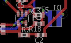
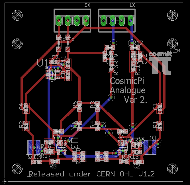
Analogue front end circuit design.
What is on the board?
The board is a 50x50 two layer PCB. On the bottom side it has pads for two Advansid ASD-NUV3S-P SiPM's and two Molex 2.54mm pitch connectors (pinned out to be suitable for connection to an Arduino DUE, provided you find a bias voltage elsewhere for the SiPMs). On the top side it has two AD8014 SOT-23 amplifiers, connected as voltage mode amplifiers and a dedicated 4V linear low drop-out regulator. The reason for the additional voltage rail is to isolate high frequency noise (achieved in theory by having two ferrites and no ground/voltage plane on the PCB).
How does it fit together?
The idea is that this PCB will be glued on top of a scintillator slab (dimensions 65x65 or greater, 10mm thickness), which will then be wrapped in a reflective foil. The two Molex style pin headers will be used to connect and mechanically fasten it to the main PCB, which will be a 100x120mm dual layer board. Six additional holes are provided for small nylon fixing bolts, however only 4 are positioned for use in this typical configuration, the other two are provided just in case someone wants to plug it in differntly. As part of final assembly, the board will be connected to the scintillator at the SiPM modules using a bubble free (vacuum mixed) optical adhesive (basically an epoxy).
What else?
In the zip file we have also provided an LT Spice model, which has been used to pick the component values. There are typically two modes for operating an SiPM: Voltage or Current. Current mode is preferred as it preserves the fast response time of the device which is ideal for timing applications (typically PET, but it would also be nice for Cosmic Pi). In the current configuration of our design we are using voltage mode, as it's simpler to model and higher voltage gains can be achieved with a single stage (the more observant will already know that our initial analogue prototypes (EagleCAD format) had 3 stages of amplification, followed by 2 stages of pulse shaper). This design provides amplification and some pulse shaping in a single stage. There are 0 Ohm and NM (Not Mounted) components on the PCB that enable it to be re-configured for transimpedance operation, which is something we would like to try in the future. This masters thesis provides a great description of the details of transimpedance amplifiers for SiPM applications.
Revised front end amplification stage
Does it work yet?
We don't know! We've ordered the PCB's and the parts, we will assemble them as soon as we can and test it. Until then, build at your own risk! You can download the zip file containing the Eagle CAD files, gerbers, BOM and LT Spice model here. If you do build it we would love you to share your feedback with us. For reference we are using a BC-408 equivalent scintillator called EJ-200. We expect to test it around the end of August 2016. If you have any questions please don't hesitate to get in touch!
Update - the design files have been changed a little and the links updated. We received the circuit boards on the 15th August and plan to have them tested by the end of the month. Watch this space for future updates!