Cosmic Progress - Shenzhen edition
Over the last few weeks a lot of things have happened!
Two summer students joined us over the last two months. Darko from Serbia and Tong from China. Both were part of the Geneva Tsinghua Initiative Sustainable Development Goals Summer School. And since August another student, Hendrik, has joined us and will be with us until mid of October.
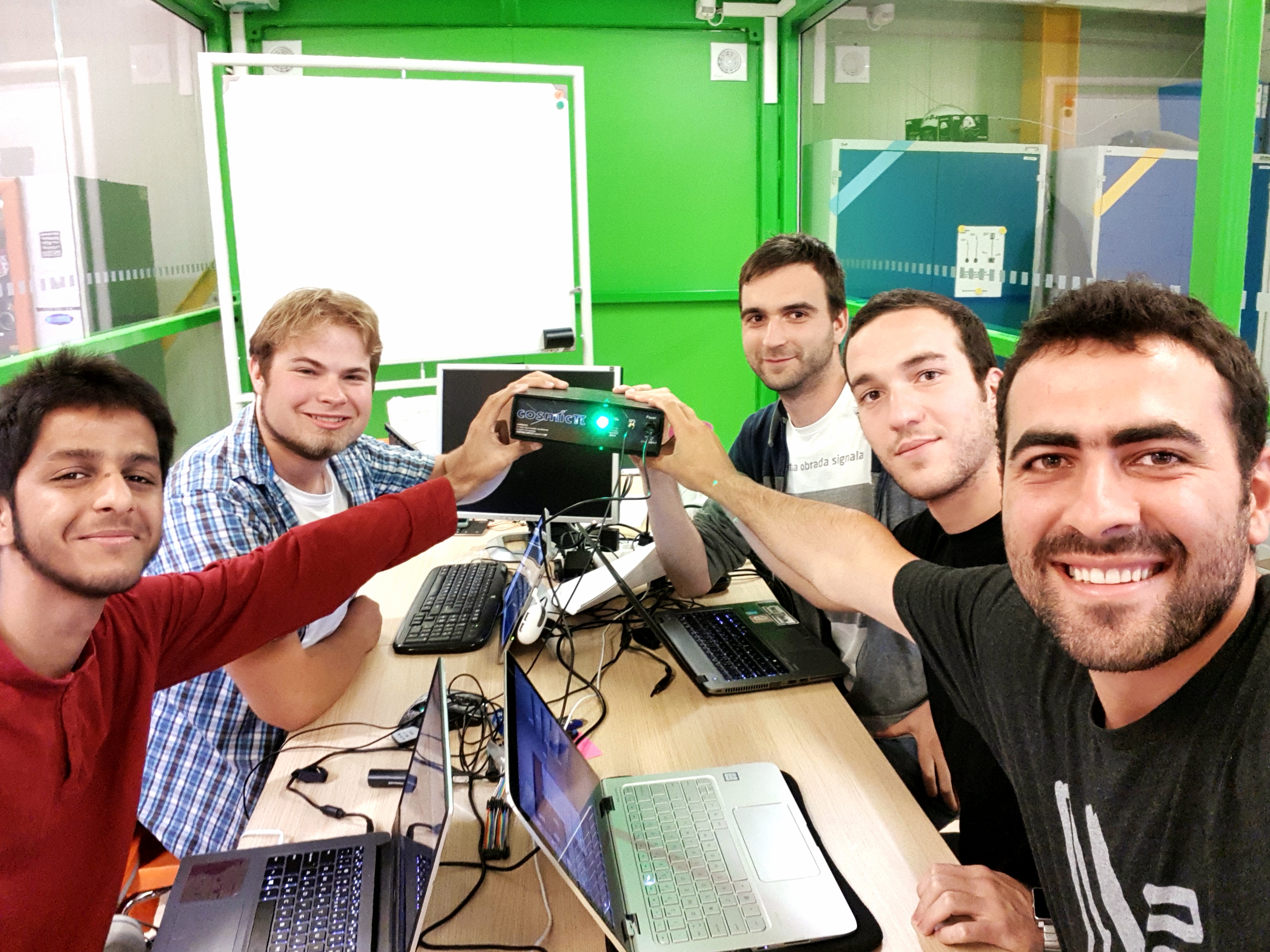
Summer student group with version 2 mockup at Ideasquare. From left to right: Shrey, Hendrik, Darko, Faouzi, Oday (missing: Tong).
So what have we worked on over the last few months?
First of all, we moved our website from an old WordPress instance to GitHub. Next a lot of time has been spent on designing the next version of CosmicPi, as well as an intermediate step to allow the electronics and performance to be tested. For the near future (i.e. the end of this year) an intermediate is planned, which we're calling V1.5. This version will improve on the existing design using the Arduino DUE. Mainly by replacing the analogue amplifier board and improving the power supply for the silicon photo-multipliers (SiPM's). In order to improve the power supply we decided to use two low noise boost converters, providing an independent supply for each sensor on our version 1.5 release. Our new team member Louis has designed a completely new power supply circuit featuring an increased voltage range and higher resolution, which we'll be sharing the schematic once we've integrated it into a prototype PCB. During the same timeframe, another new team member Nikolai has re-designed the analogue amplifier board from the V1 release to employ transimpedance amplification principles. The new design can be found here.
A first batch of the new analogue board has already been assembled and is currently being tested by the team. So far the results are promising.
And you can read more about it in our last post!
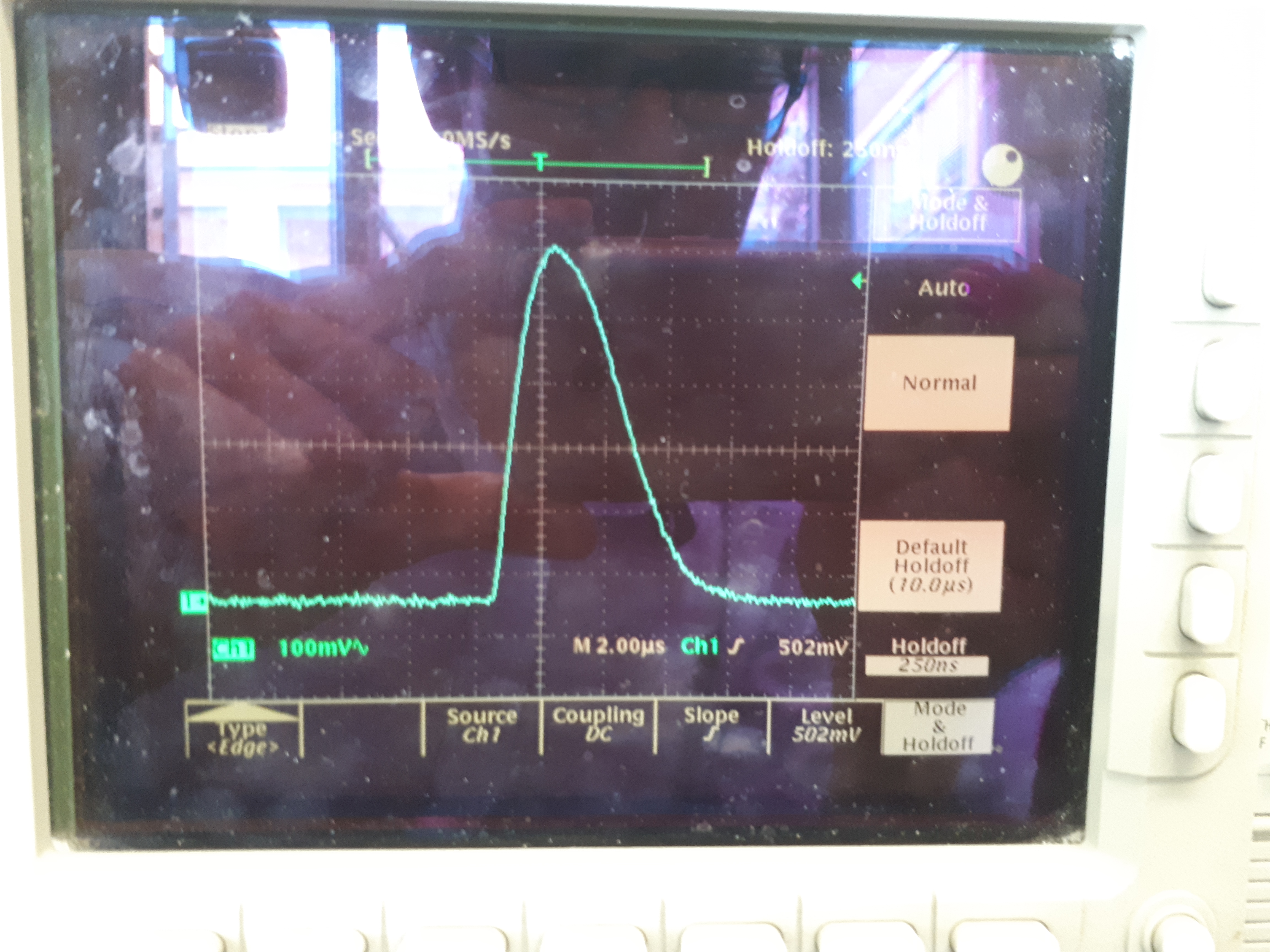
Recorded spike of a triggered SiPM with the new analogue board. The spike is nicely amplified into an area of a few 100mV and minimal additional noise is introduced. Note that the timebase is wrong, it should be 200ns.
At the same time we are working on a Version 2 of CosmicPi. The Version 2 will build on many of the design elements of the Version 1.5, such as the improved analogue board whilst introducing our new power supply design. The Version 2 will move away from the Arduino DUE and the current digital hardware model for data acquisition. Instead a FPGA will be used to read out two high speed analog to digital converters (ADC), which run at approximately 100 MHz. With these ADCs the amplified signal from the SiPM's can be read directly, without the need for a pulse shaper as in our Version 1 design. This will improve the precision of the received data as well as providing more options to analyze the data we get from the SiPM's. The FPGA is then directly connected to a single board computer (SBC) such as the Raspberry Pi (or the lower cost Orange Pi) via GPIO-Pins. All other sensors, such as GPS, accelerometer and the temperature sensor will be read out by the single board computer, since this is not time critical like the SiPM readout.
Darko has been working a lot on the software for the FPGA. He has taken the first steps in validating a design for the software and implementing this into VHDL. The high level design can be seen below and the corresponding code can be found here.
Design for the FPGA software
It is fair to say that this version will still take some time until it is up and running. At the moment we are working from two Lattice FPGA iCE40HX8K development boards. However over the last few weeks we already designed a first version of the hardware main board for the Version 2 CosmicPi. Six prototypes of this board are now being produced by Seeed Studio in Shenzhen and will be arriving any day at our lab. Having a Raspberry Pi (or equivalent SBC hardware) as an integral part of the detector gives us more options in developing the user experience and interaction possibilities. Hendrik has started designing the software that is going to run on the Raspberry Pi.
Design for the software running on the raspberry pi
In order to test and develop this software without having the FPGA ready yet we decided to build a mockup of the Version 2 CosmicPi. The mockup uses a Raspberry Pi 3 to run the software and has a GPS, temperature sensor, pressure sensor and a 9 DOF integrated measurement unit connected to it - the only thing missing is the custom cosmic ray detection hardware. In this way, most of the software can already be developed for the Version 2 design, with only the connection to the FPGA to add when the hardware is available.
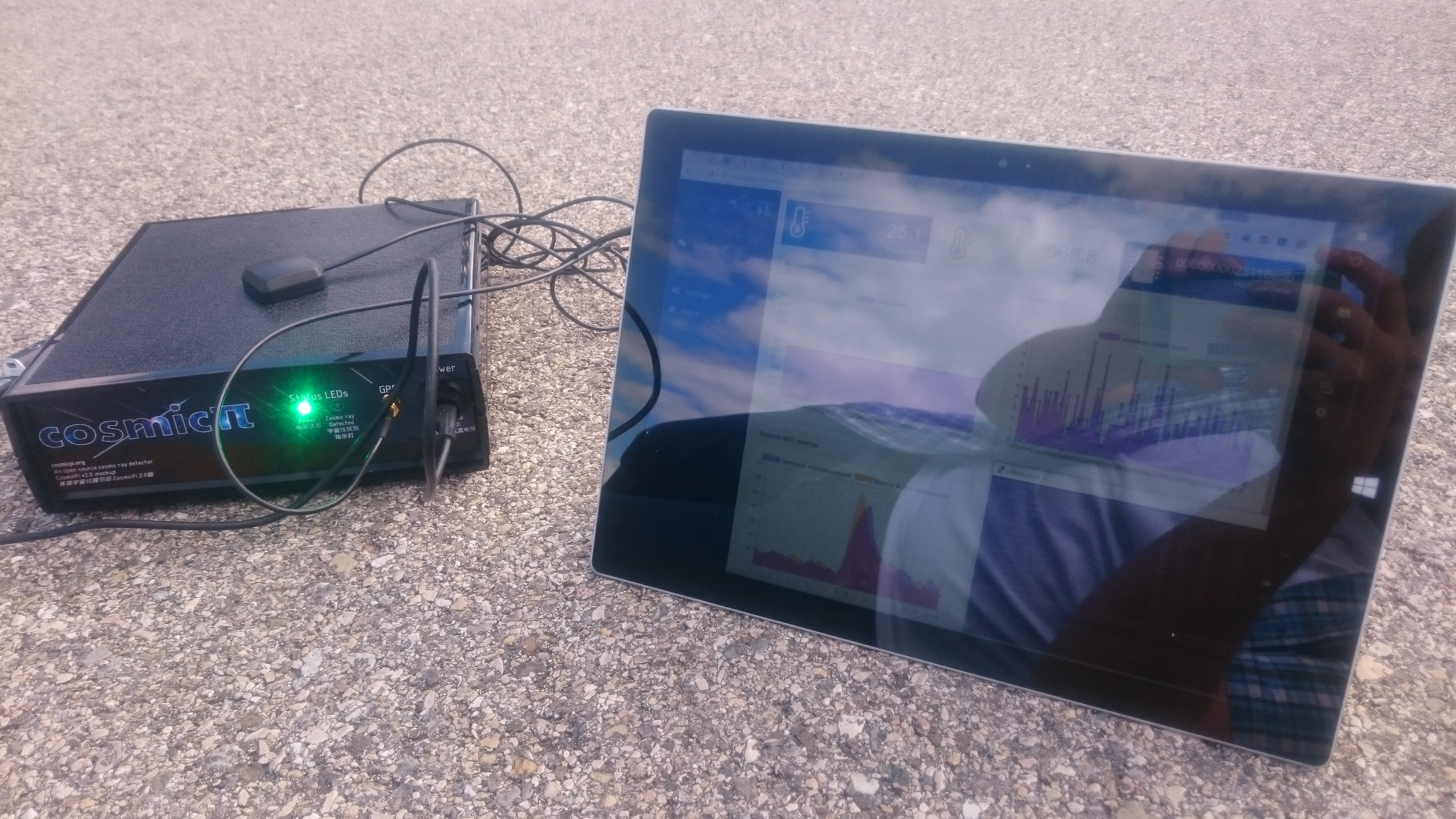
Version 2 mockup with Surface showing the user interface
Recording of the user interface
You can take a look at the software here.
A part of the GTI SDG-Summer school was as a two weeks trip to China for Darko and Tong, with Hendrik staying for a total of four weeks. During this time a lot of engagement work with the Chinese general public was done. This is why the Version 2 mockup is completely bilingual, supporting both English and Chinese! In Beijing and Shenzhen we gave multiple presentations on CosmicPi and in Shenzhen had a poster session with students and teachers from the area.
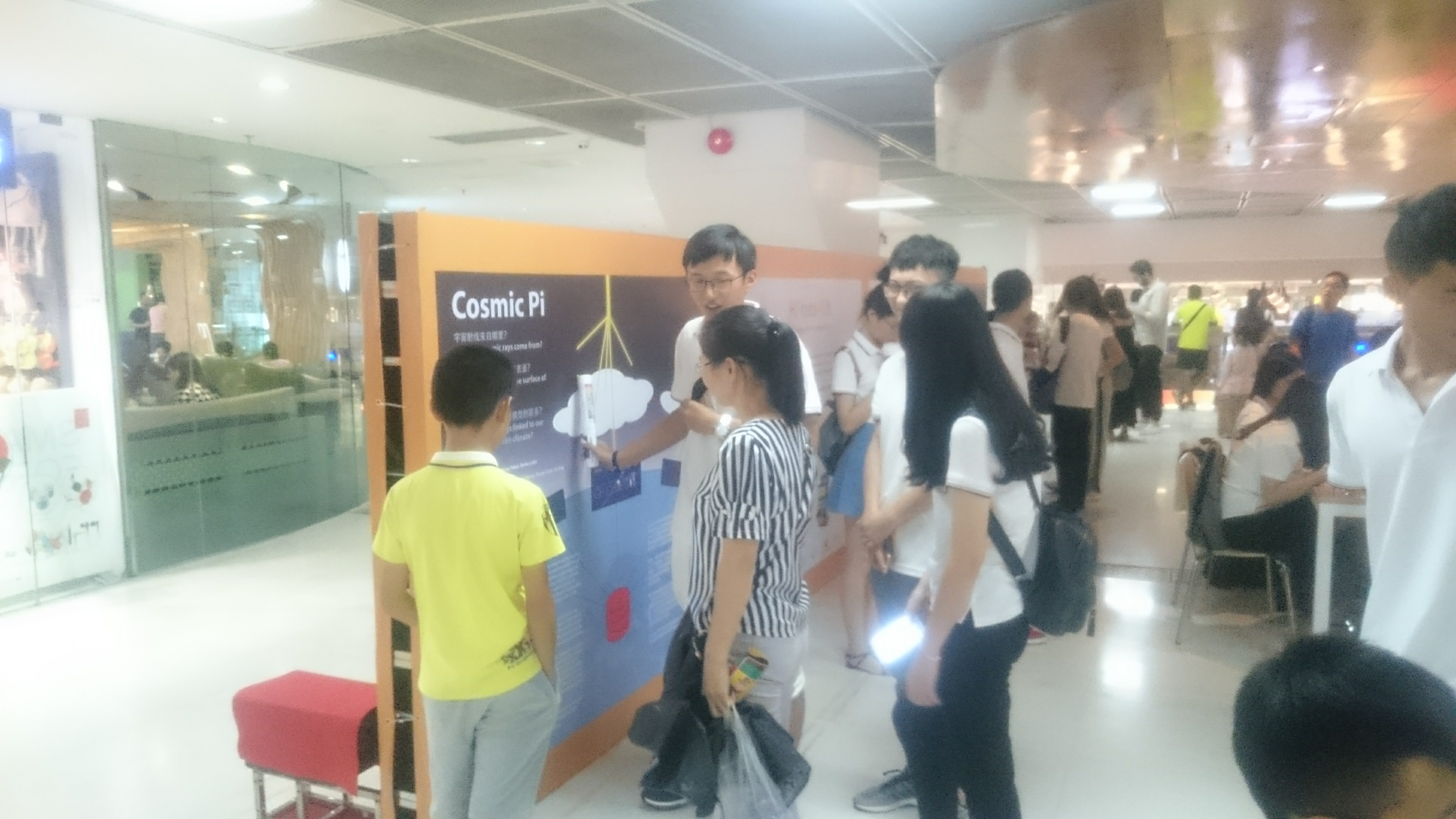
Poster session in Shenzhen
Shenzhen is a great city for hardware development and we wanted to see if an extended stay there could be useful for the project. In general hardware and hardware production means are readily available there. While James, Darko and Tong stayed in Shenzhen for one week, Hendrik was able to stay two weeks longer.
Rather disappointingly "special" parts, such as scintillators and SiPM's (which are only really used for High Energy Physics applications) are very hard to find there. So we decided to explore different ways of detecting cosmic rays without scintillators, using silicon - of which there is an abundance in Shenzhen. One approach we evaluated was to use CMOS or CCD sensors for directly detecting ionizing particles. These sensors can be extremely cheap, with CMOS image sensors as used in smartphones available from as little as 50 cents each. However the cheaper sensors require advanced manufacturing methods for the PCB (4 layers with blind vias), making small volume prototyping for this approach very expensive.
Another detection technology that has been popular among enthusiasts for some time now is the use of pin-diodes. As an example, the BPW34-diode have been used for particle detection in many projects and the needed parts are readily available in Shenzhen and through the international electronics supply chain. Over the last few weeks Hendrik and James have thus been discussing and designing such a detector. The resulting board design can be seen in the picture below.
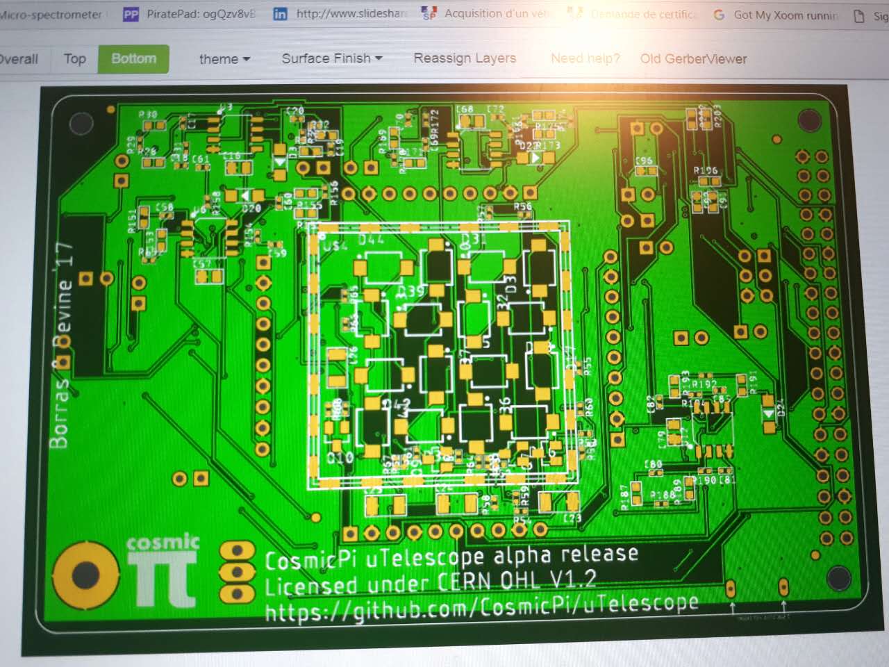
Back of the pin-diode detector
The detector has 16 diodes on the top of the PCB and 16 on the back to allow coincidence triggering. After the signal of the diodes is amplified the readout is done by an Atmel 328 microprocessor, exactly the same chip that is the core of every Arduino UNO. The final data acquisition and user interface is then again provided via a single board computer. The circuit design can be found here.
Some prototypes of this detector are also currently in production at Seeed Studio. We hope that we can start testing it soon, and of course we will share the results with you as soon as we can!